
Architecture & design stage simulation
Smart design instead of re-design
During the architecture and design stage, simulation can be used to compare for example different design approaches; a detailed layout of the mechanical system can then be created for the best approach. The use of software models makes it possible to represent dynamic properties, accurately predict actual loads, and optimally define the size of the mechanical support structures. Throughput predictions are also possible.
Using simulation to design a robot mechanism
Real-world example from the packaging industry
Initial situation:
Development of an application-specific robot for palletizing tasks integrated in palletizing cells. Search for an open robot control system able to address the task-specific challenge. The standard robot was not suitable due to the limited space for installation, and good accessibility of the palletizing positions.
The solution:
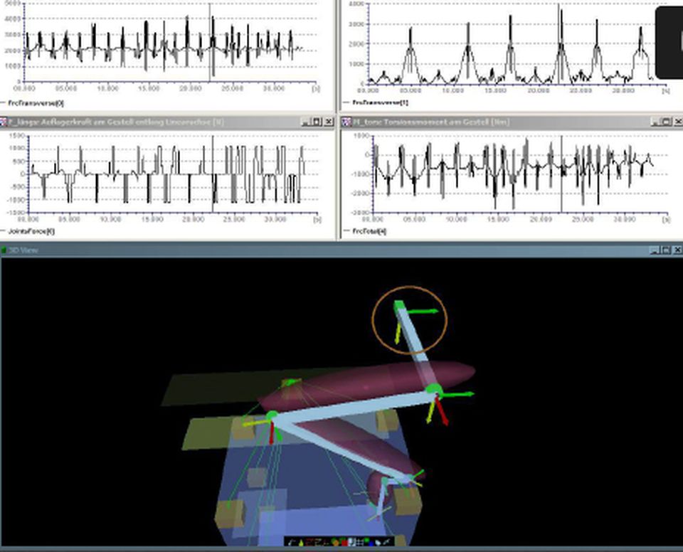
Simulation was used to compare different design approaches; a detailed layout of the robot mechanism was then created for the best approach.
Details on the solution:
The simulation identified all relevant forces and moments for the mechanical design as well as the dynamic behavior during operation and in exceptional situations (such as emergency stop).
Result/savings:
The robot was implemented according to the simulation, and its behavior matched the predictions exactly. There was no need for complex iterations in the development of the mechanism, and the time-to-market and the development costs remained far below the projections.
Implementation time:
The preparations for the project took 3 months, the implementation of the environment simulation 2 weeks.
Firmware simulation model for pitch drives
Real-world example from wind turbine manufacturing
Initial situation:
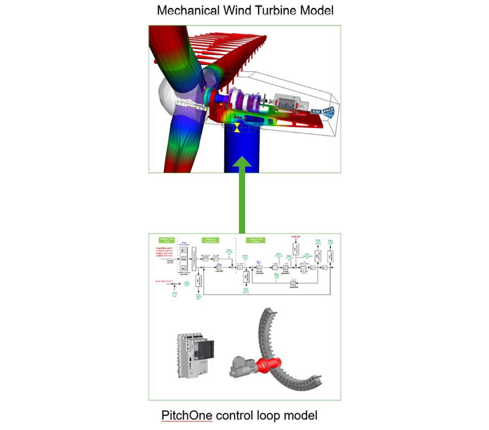
The dynamic properties of the electromagnetic drive train for pitch angle adjustment in wind turbines must be taken into account for the dimensioning of the mechanical support structure of the wind turbine. Due to various non-linear limitation functions in the internal control loops of the drive, a simple substitution model (e.g. a simple time-delay element) is not sufficient to represent the dynamic.
The solution:
A software model was derived from the pitch drive firmware. It represents all essential dynamic properties and can be integrated into the simulation tools of the wind turbine manufacturers.
Details on the solution:
The model represents the jerk-limited position profile generator, the drive control loops as well as the transmission ratio. The conversion of the position setpoint profile into the actual position is thus represented with very high precision. The parameter configuration of the model can be taken from the parameter data records of the actual application.
Result:
The actual loads can be predicted more accurately. Unnecessarily high design reserves can thus be omitted, resulting in cost savings.

Thank you for your request. Our KEBA Customer Support will get in touch with you soon.


